


Structural health assessment in civil engineering is a process to assess the condition of a structure to detect damage, evaluate its severity, and predict its future performance. The primary goals are to prevent catastrophic failures, optimize maintenance and repairs, extend the lifespan of structures, and ensure safety.
Common Health Assessment Techniques
- Condition Survey
- Testing (NDT)
- Structural Analysis and Gap Study
- Condition Survey: A condition survey of a building is a systematic and detailed inspection by a qualified professional to assess the physical state, structural integrity, and overall condition of a property. It is used to identify defects, potential problems, and necessary repairs, and to help property owners, buyers, or managers make informed decisions about maintenance, sales, or renovations.
A building condition survey typically covers several key elements of a building, including:
- Structure: The survey will inspect the building’s foundation, walls, floors, and roof to identify any structural defects or issues that need to be addressed.
- Exterior: The survey will evaluate the condition of the building’s exterior, including the walls, windows, doors, and roofing.
- Interior: The survey will examine the interior of the building, including the walls, floors, ceilings, electrical and mechanical systems, and any other relevant features.
- Services: The survey will inspect the building’s electrical, plumbing, and HVAC systems to ensure they are in good working order and identify any issues that need to be addressed.
- Safety and accessibility: The survey will evaluate the building’s compliance with safety and accessibility regulations, and will identify any issues that need to be addressed.
- Fire protection: The survey will evaluate the building’s fire protection systems, including alarms, sprinklers, and smoke detectors, and identify any issues that need to be addressed.
- Energy efficiency: The survey will evaluate the building’s energy efficiency, including its insulation, lighting, and heating and cooling systems, and identify any areas where improvements can be made.
- Site and surroundings: The survey will evaluate the condition of the building’s site and surrounding areas, including car parking, playgrounds and landscaping
- Testing : NDT
This exercise for studying the possible ways to retrofit the existing building to meet possible working loads and seismic loads undertaken after evaluating the non- destructive study results conducted on the building, crack and deflection patterns recorded from the site.
The non-destructive study results will indicate whether the building is under overstress stage in multiple structural components. This exercise will find ways to retrofit the building to the desired strength levels and make it capable to function as a post disaster building incase deficiency is encountered due to design deficiencies or load in basements.
This study, the first step in the retrofitting design is to find the members over stressed, possible techniques to reduce the stresses on the building components and possible methods to strengthen those components.
The building structure needs to be analysed in multiple iterations to find ways to satisfy the required strength characters of members.
As the first attempt, the building is analysed and designed as per existing architectural drawings and loadings as the current use of the building. After studying the results and available section properties of members, other options are studied with varied section properties and additional members to reach the goal.
The following fields as well as laboratory non-destructive tests are proposed to be carried
out as per location mentioned under client’s scope.
- Field Tests
- Schmidt’s rebound hammer tests for determining the concrete compressive strength.
- Ultrasonic pulse velocity tests for establishing the quality of concrete.
- Rebar locator tests for locating rebars and for determining rebar dia (wherever possible) and rebar spacing.
- Carbonation tests for determining the depth of carbonation of concrete.
- Drilling out of concrete cores from various RCC members of the structure for determining concrete compressive strength.
- Cover Meter tests for determining thickness of concrete cover.
- Laboratory Tests
- Preparation and testing of drilled out concrete core specimens for determining concrete compressive strength in the lab.
DETAILS OF TESTS:
2.1 Rebound Hammer Test
The rebound hammer test will give concrete compressive strength at several locations. A site-specific correlation will be developed between the rebound number (obtained directly from the rebound hammer) and the actual in-situ concrete strength obtained from the core tests. This correlation would be used to determine the concrete strength at several locations where rebound tests would be done.
Some of the objectives of Rebound Hammer test are as follows:-
- To assess quality of concrete in relation to the standard requirements.
- To estimate compressive strength of concrete with the help of suitable correlations between rebound index and compressive index.
- To delineate regions of poor quality or deteriorated concrete in a structure.
- To assess quality of one element of the concrete in relation to another. Factors affecting the test results:-
- Type of cement
- Type of aggregate
- Surface condition and moisture content of concrete
- Curing and age of concrete
- Carbonation of concrete surface
The test is based on the principle that the rebound of an elastic mass depends on the hardness of the surface against which mass strikes.
The plunger of hammer is pressed strongly and steadily against the concrete surface at right angles to its surface, until the spring loaded mass is triggered from the locked position.
The distance travelled by the mass as a percentage is defined as rebound number.
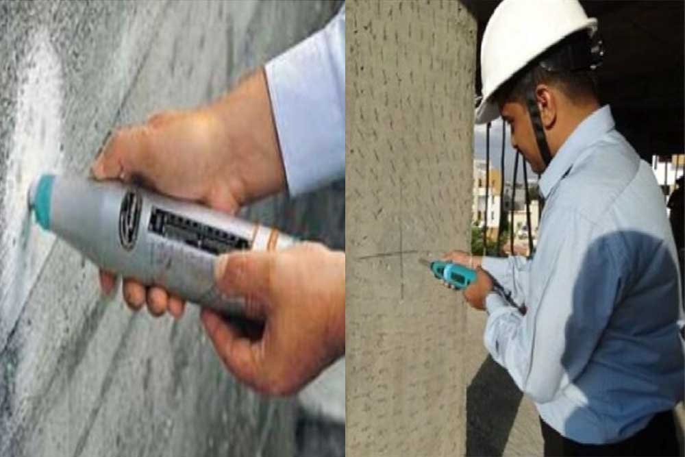
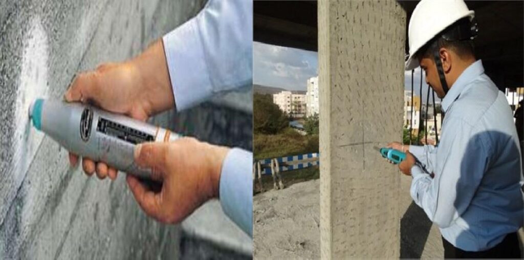
Fig.1: Rebound hammer
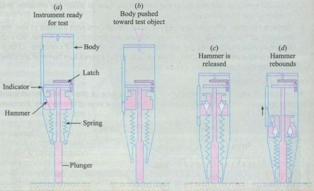
Fig.2: Image showing mechanism of Rebound Hammer
Fig. 3: A man performing Rebound Hammer Test
Interpretation of the Test Results:
| Average Rebound Number | Quality of concrete |
| More than 40 | Very good very hard layer |
| 30 to 40 | Good layer |
| 20 to 30 | Fair |
| Less than 20 | Poor concrete |
| 0 | Delaminated |
Steps to carry out Rebound Hammer Test:
The test is performed as per guidelines given by IS: 13311 (Part 2): 1992 to estimate the in situ strength of concrete based on the correlation established between in-situ strength at the particular location & rebound numbers.
- The plaster is removed at test locations.
- For testing, smooth, clean, dry surface without any defect like Honeycombing cracks and hollow sound is selected.
- The area of approx. 300 mm x 300 mm is rubbed with carborundum stone to remove loosely adhering scales, or remains of plaster mortar, if any.
- In this area 12 points at approximate 30 mm apart are selected in grids.
- By holding the rebound hammer at right angles to surface of the concrete member, 12 readings are taken at selected points.
- Of these readings, abnormally high & abnormally low results are eliminated & average of the balance readings is worked out.
- Taking into consideration the factors influencing hardness of the concrete surface like moisture condition of the surface, carbonation, test location within the member, direction of test etc. corrected rebound number is worked out.
- The compressive strength of concrete against each rebound number is obtained from graph prepared on correlation established between rebound numbers at core test locations & equivalent cube strength values.
- The statistical analysis is carried out for this set of values of compressive strengths obtained by above method.
- Concrete Core Test
This is one of the very reliable tests adopted for checking the compressive strength
of the ‘In situ concrete”.
Other physical properties such as density, water absorption can also be measured from the core concrete.
In addition chemical properties of concrete specimen for its cement content, carbonation depth, chloride and sulphate content may be measured.
Steps to the Core Tests:
The reinforcement is detected at planned location with the help of Rebar Locator called Profometer to avoid cutting of reinforcement.
- The Core cutting equipment is fixed at the planned location & core is extracted.
- The Cores are transported to the laboratory & visual observations of cores are recorded for interpretation purpose. Reinforcement bars, if encountered, are cut off.
- The Cores are removed from water cut to the required L/D ratio of 2, wherever possible, exactly perpendicular to the longitudinal axis.
- Both the ends are prepared by grinding up to the tolerance limit as specified by Clause 4:8 of BS 1881: Part 120: 1983 for flatness & parallelism.
- A thin layer of plaster of Paris is applied to ends to ensure proper contact.
- Now the cores are ready for compression testing.
2.3 Ultrasonic Pulse Velocity Test (UPV)
The ultrasonic pulse velocity measurements will give information about concrete quality, in terms of ultrasonic pulse velocity, voids, flaws, cracks, honeycombing etc. as also depth of cracks in structural members. The results would help in identifying the areas required to be strengthened.
The method consists of measuring the time of travel of an ultrasonic pulse passing through the concrete being tested. Comparatively higher velocity is obtained when concrete quality is good in terms of density, uniformity, homogeneity etc. The ultrasonic pulse velocity test is per guidelines given in IS: 13311 (Part 1) – 1992.
Some of the objectives of Ultrasonic Pulse Velocity test are:-
- To assess uniformity and homogeneity of concrete.
- To assess quality of concrete in relation to standard requirements.
- Detection of presence and approximate extent of cracks, voids and other imperfection in concrete.
- Measurement of changes occurring with time in the properties of concrete.
- Correlation of pulse velocity and strength as a measure of concrete quality. Factors affecting test results:-
- Smoothness of contact surface under test.
- Influence of path length on pulse velocity.
- Temperature of concrete
5°- 30° Ideal
30°- 60° (Reduction in UPV up to 5%)
Below 5° (Increase up to 7.5%)
- Moisture content of concrete (Pulse velocity is proportional to moisture content).
- Presence of reinforcing steel (UPV of reinforcement is 1.2 to 1.9 times of normal concrete).
- Stress level in concrete.
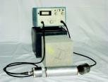
Fig.4: Ultrasonic pulse velocity meter
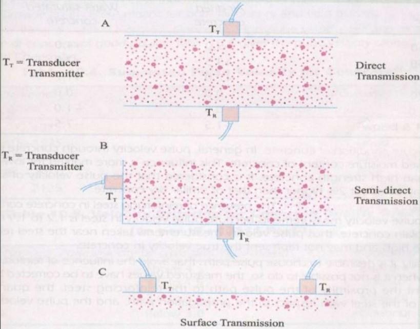
Fig.2.5: Measurement Techniques for Pulse Velocity test
Steps to carry out the USPV test:
- The plaster is removed at test locations wherever required.
- For testing, smooth, clean, dry surface without any defect like honey combing, cracks, and hollow sound is selected.
- The area of approx. 300 mm x 300 mm is rubbed with carbonation stone to remove loosely adhering scales, or remains of plaster mortar, if any.
- Two points are marked on opposite faces of the concrete members. (At exactly opposite locations for direct transmission of ultrasonic pulses).
- Grease is applied as a coupling medium to ensure proper contact of the transducers with concrete surface so that ultrasonic pulse is transmitted through the medium without much disturbance.
- Now both the transducers are held at correct test locations by applying constant pressure & ultrasonic pulses are transmitted through the concrete.
- The machine displays the time taken to travel the known path in microseconds.
- The velocity is calculated from the reading obtained against each known path.
The mean value of the display readings should be taken when the unit’s digit hunts
between two values.
Pulse velocity = Path length /Travel time
Separation of transducer leads: It is advisable to prevent the two transducer leads from coming into close contact with each other when the transit time measurements are being taken. If this is not done, the receiver lead might pick-up unwanted signals from the transmitter lead and this would result in an incorrect display of the transit time. The quality of concrete in terms of uniformity, incidence or absence of internal flaws, cracks and segregation, etc., indicative of the level of workmanship employed, can thus be assessed using the guidelines given below, which have been evolved for characterizing the quality of concrete in structures in terms of the ultrasonic pulse velocity.
Following velocity criterion for concrete quality grading is given by IS 13311 (Part I): 1992. Criterion for grading of Concrete Quality
| Ultrasonic Pulse Velocity by Crossprobing (Km/Sec.) | Concrete Quality Grading |
| Above 4.5 | Excellent |
| 3.5 to 4.5 | Good |
| 3.0 to 3.5 | Medium |
| Below 3.0 | Doubtful |
2.4 Rebar Locator or Cover Meter Survey Test (PF)
The Cover Meter tests will give thickness of the clear cover over reinforcement bars. The cover values will be used for determining the risk of corrosion together with the results of the carbonation tests.
The primary objectives of rebar locator are:-
- To assess location of reinforcing bar.
- To determine size of reinforcing bar.
- To assess concrete cover. Factors affecting test results:-
- Cover measurement may be affected by neighboring bars parallel to the end of bar being measured.
- Variations in the properties of steel.
- Cross-sectional shape of bars.
- Roughness of the surface.
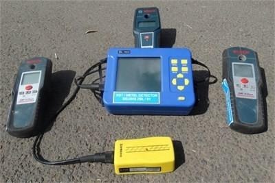
Fig.2.6: Rebar Locator Equipment set
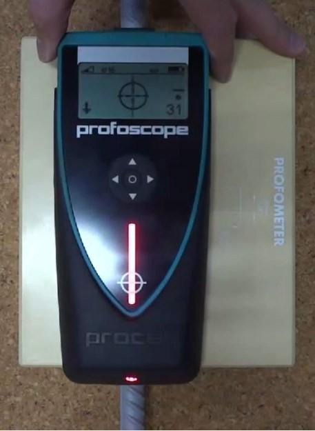
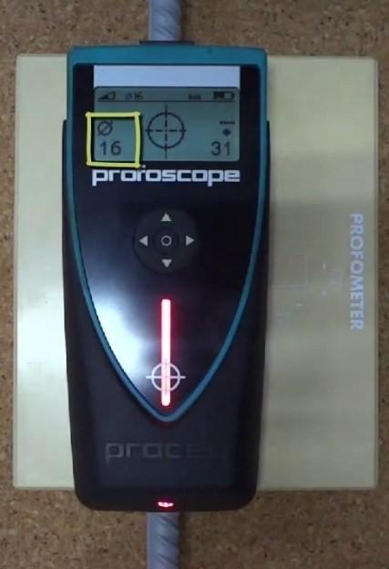
Fig.2.7: Estimating location of rebar Fig.2.8: Estimating rebar diameter
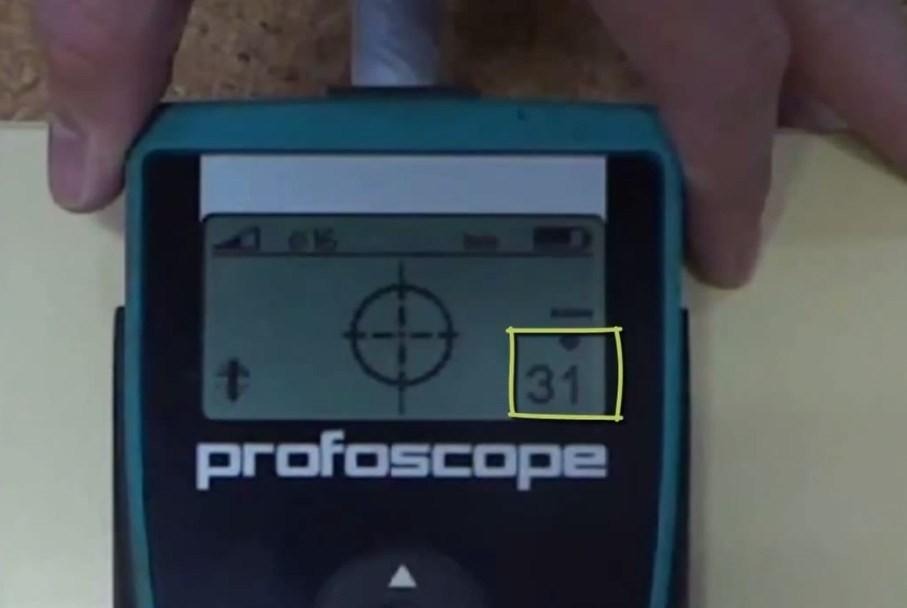
Fig.2.9: Estimating concrete cover
The reinforcement bar is detected by magnetising it and inducing a circulating “eddy current” in it.
After the end of the pulse, the eddy current dies away, creating a weaker magnetic field as an echo of the initial pulse.
The strength of the induced field is measured by a search head as it dies away and this signal is processed to give the depth measurement.
The eddy current echo is determined by the depth of the bar, the size of bar and the orientation of the bar.
This detection of location of reinforcement is required as a pre-process for core cutting.
2.5 Carbonation Tests
The carbonation tests will help in determining the risk of corrosion to the reinforcement bars & affording confidence in the durability of concrete.
To evaluate extent of carbonation for strength and corrosion estimation.
Carbonation of concrete occurs when the carbon dioxide, in the atmosphere in the presence of moisture, reacts with hydrated cement minerals to produce carbonates Within a few hours, or a day or two at most, the surface of fresh concrete will have reacted with CO2 from the air. Gradually, the process penetrates deeper into the concrete at a rate proportional to the square root of time.
After a year or so it may typically have reached a depth of perhaps 1 mm for dense concrete of low permeability made with a low water/cement ratio, or up to 5 mm or more for more porous and permeable concrete made using a high water/cement ratio.
The affected depth from the concrete surface can be readily shown by the use of phenolphthalein indicator solution. This is available from chemical suppliers. Phenolphthalein is a white or pale yellow crystalline material. For use as an indicator it is dissolved in a suitable solvent such as isopropyl alcohol (isopropanol) in a 1% solution.
The extent of carbonation is determined by testing concrete surface with a 1% phenolphthalein solution
The 1% phenolphthalein solution is made by dissolving 1gm of phenolphthalein in 90 cc of ethanol & the making it to 100cc by adding distilled water
Steps for carbonation test
The phenolphthalein indicator solution is applied to a fresh fracture surface of concrete and observed for 10mins.
If the indicator turns purple, the pH is above 8.6. Where the solution remains colourless, the pH of the concrete is below 8.6, suggesting carbonation. A fully- carbonated paste has a pH of about 8.4.
Change in colour is observed after test
| Change in colour | Inference |
| No change in colour layer | Carbonation affected |
| Purple | No carbonation has taken place |
Carbonated Concrete
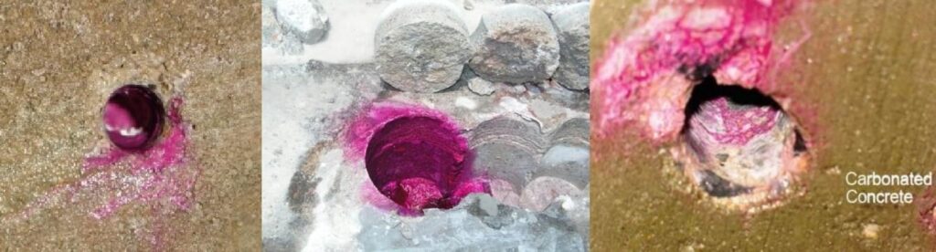
Fig.2.10: Images showing Carbonated concrete
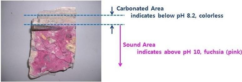
Fig.2.11: Result inference from concrete colouring
2.6 Half Cell Potentiometer Test
This test is used to assess the corrosion conditions in a reinforced concrete structure as per ASTM C876 – 91.
The apparatus includes copper-copper sulphate half-cell, connecting wires and a high impedance voltmeter
External cathode is provided in the form of copper rod and copper sulphate solution in the cell. Any point on reinforcement bar inside the concrete body functioning as anode when connected electrically to cathodic half-cell generates e.m.f. This is measured by connecting a milli-voltmeter in the circuit.
Steps for performing half-cell potentiometer test:-
- Locate the steel and determine the bar spacing using a cover meter.
- The cover concrete is removed locally over a suitable bar and an electrical connection made to the steel.
- It is necessary to check that the steel is electrically continuous by measuring the resistance between two widely separated points.
- The reinforcing bar is connected to the half-cell via a digital voltmeter.
- One electrode is connected to the bar inside concrete and the other to the concrete surface.
- Readings of half-cell potential are taken over a regular grid of points (say ½ m apart) to give a potential map of the area.
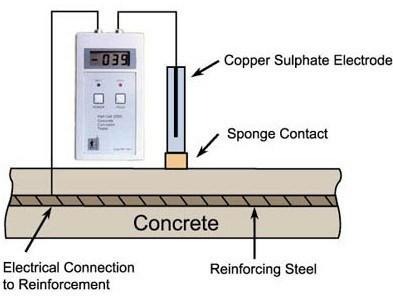
Fig.2.12: Half-cell potentiometer instrument
The possibility of active corrosion is found out according to guideline below.
| Half-cell potential (mV) reading | Percentage chance of activecorrosion |
| < -350 | 90% |
| -200 to –350 | 50% |
| > -200 | 10% |
- Structural Analysis
The analysis of the proposed structure will be done with the help of ETABS software. The frame formed in conjunction with old structural drawing. The loading and geometry of the structural system will be arrived based on existing building/ proposed changes and loads induced by the usage of the building. Seismic forces will be calculated confirming to IS 1893: 2016. The stress resultants will be interpreted and presented in graphical form.
- Gap Study, Retrofitting design and drawings
After study of health assessment report and revised structural analysis, deficiencies in individual structural members shall be worked out and suitable remedial / strengthening members shall be suggested.
Results of analysis are tabulated for the existing building under design loads, present loads with specification of materials specified in the drawings and the specification of the material obtained from NDT reports.
The tabulation will result in establishing the gap between demand and supply between the design and present structure of the building which will be further used in generating the drawings and BOQS for the type of modification required in the present building to build it at par with a healthy building.
On the basis of remedial measures, a suitable BOQ with detailed specifications of materials and items shall be devised for this particular site. It shall include preparation of all detailed method statement with drawings/ shop drawings of all different type of remedial schemes being adopted.
——————————————————————————————————————————————-
